Advanced prototyping is the heartbeat of innovation in the field of robotics, offering a dynamic platform for engineers, designers, and inventors to transform their ideas into tangible realities.
These robots find applications in various fields such as healthcare, manufacturing, transportation, logistics, and many more, making prototyping a vital step in creating solutions for real-world challenges. Robotics prototyping not only drives product improvement but also plays an essential role in assessing and managing potential risks.
In this article, we'll explore the practical application of ProtoPie in robotics prototyping. To illustrate its capabilities, we’ll create a surgical robot arm prototype that’s commonly used within the MedTech industry. I'll guide you through the process of controlling an Arduino robot arm using a wireless controller, all made possible through ProtoPie!
Overview
Prepare a robot arm
How to make the robot arm move
Connect the wireless controller
Bridge the wireless controller to Arduino
Integrate a camera feed into the UI
That’s it! The surgical robot arm prototype is complete!
Shape the future of Robotics and MedTech
💡Note: In our exclusive Robotics & MedTech webinar, we showcased a live demonstration of this robot arm. If you couldn't attend, make sure to view the recording to discover how ProtoPie streamlines the design process and to gain insights into the industry's top practices for efficient prototyping.
1. Prepare the robot arm
As we received inquiries from numerous robotics and MedTech companies regarding ProtoPie’s capabilities in robotics prototyping, we decided to demonstrate how to prototype typical use cases.
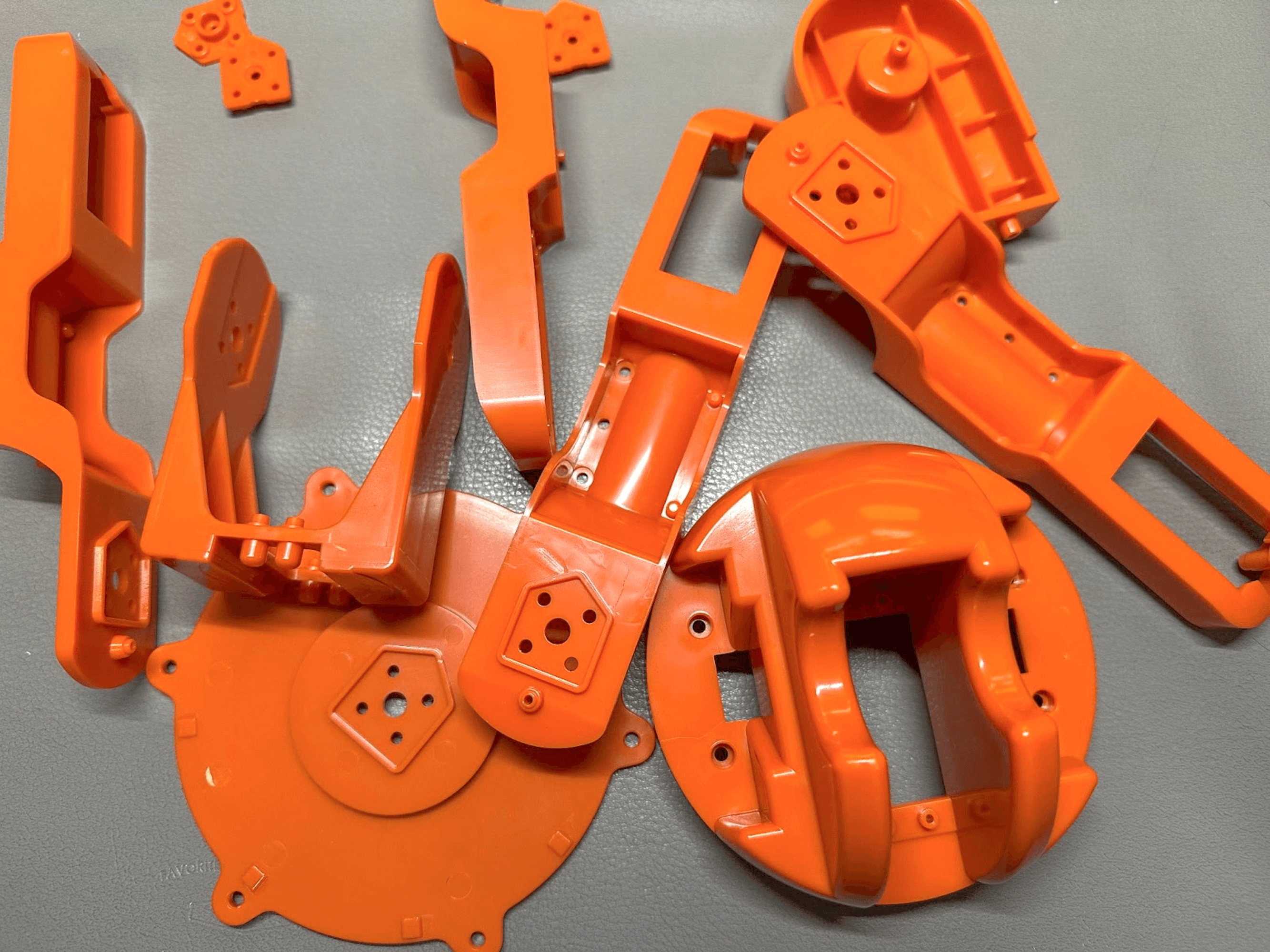
To get started, we purchased an Arduino Braccio robot arm and a wireless gamepad controller to create a surgical robot arm prototype. To give the robot arm a ‘medical robot arm’ appearance, we painted its parts white.
Robot arm before paint.
First, we started off with a grey base color.
Painting the robot arm with a grey base color.
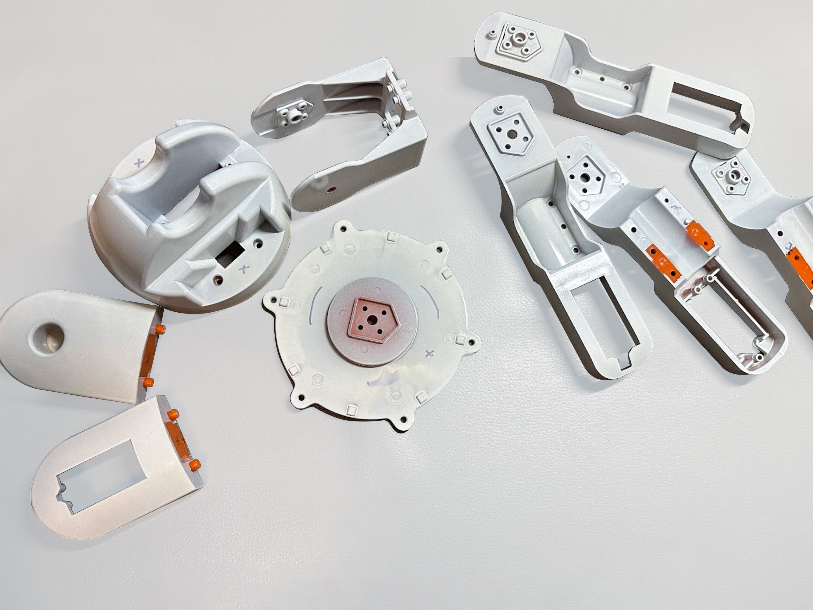
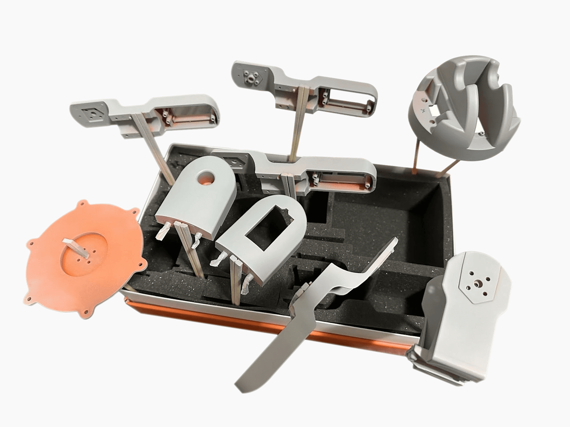
Robot arm pieces.
Finally, we painted the whole robot arm in white. The robot arm parts can be easily assembled by following the instructions it came with.
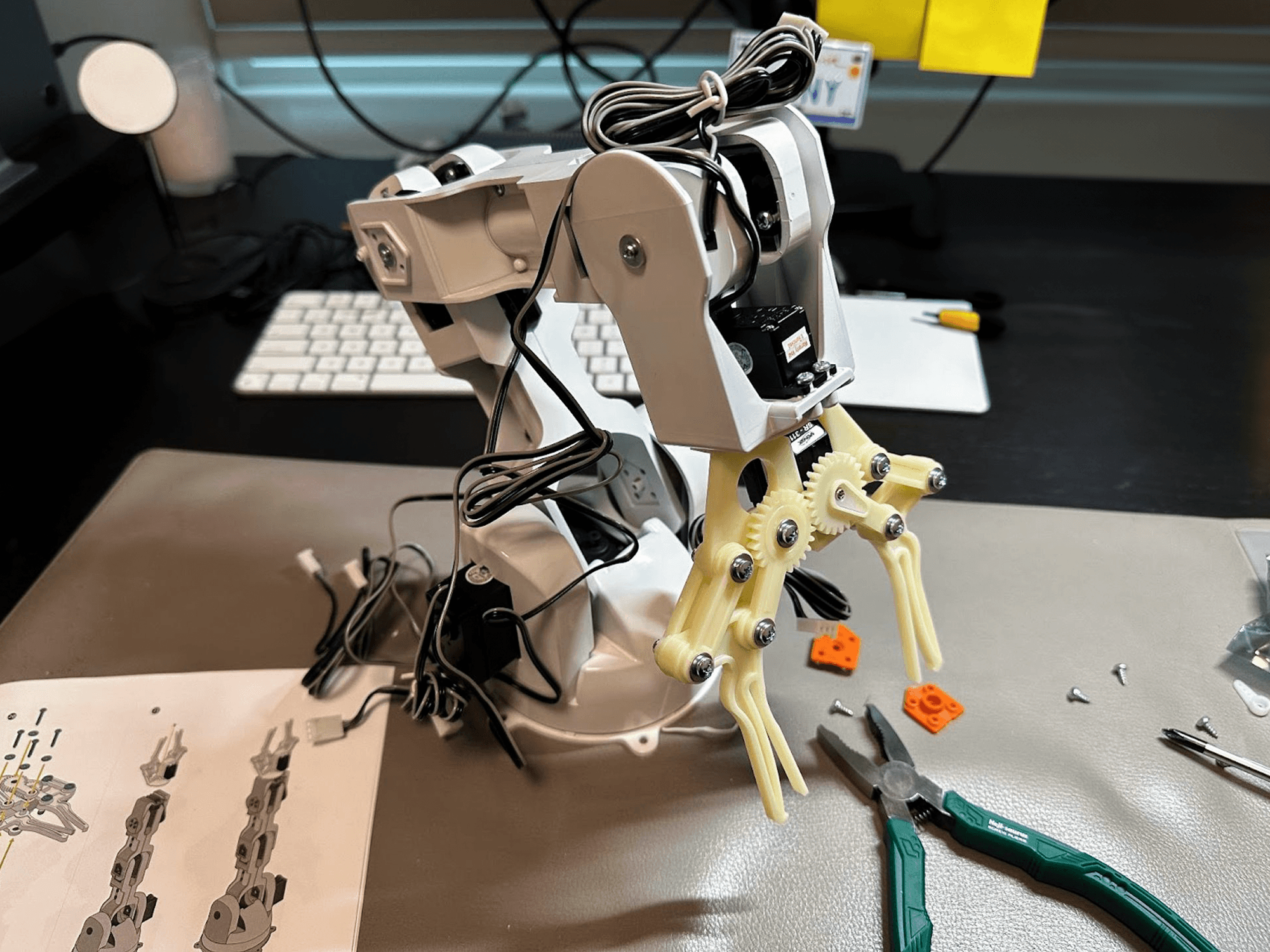
White robot arm prototype.
Since surgical robots have cameras to monitor the patient and their surroundings, we attached a USB camera module at the end of the gripper. That kind of USB camera can easily be purchased online.
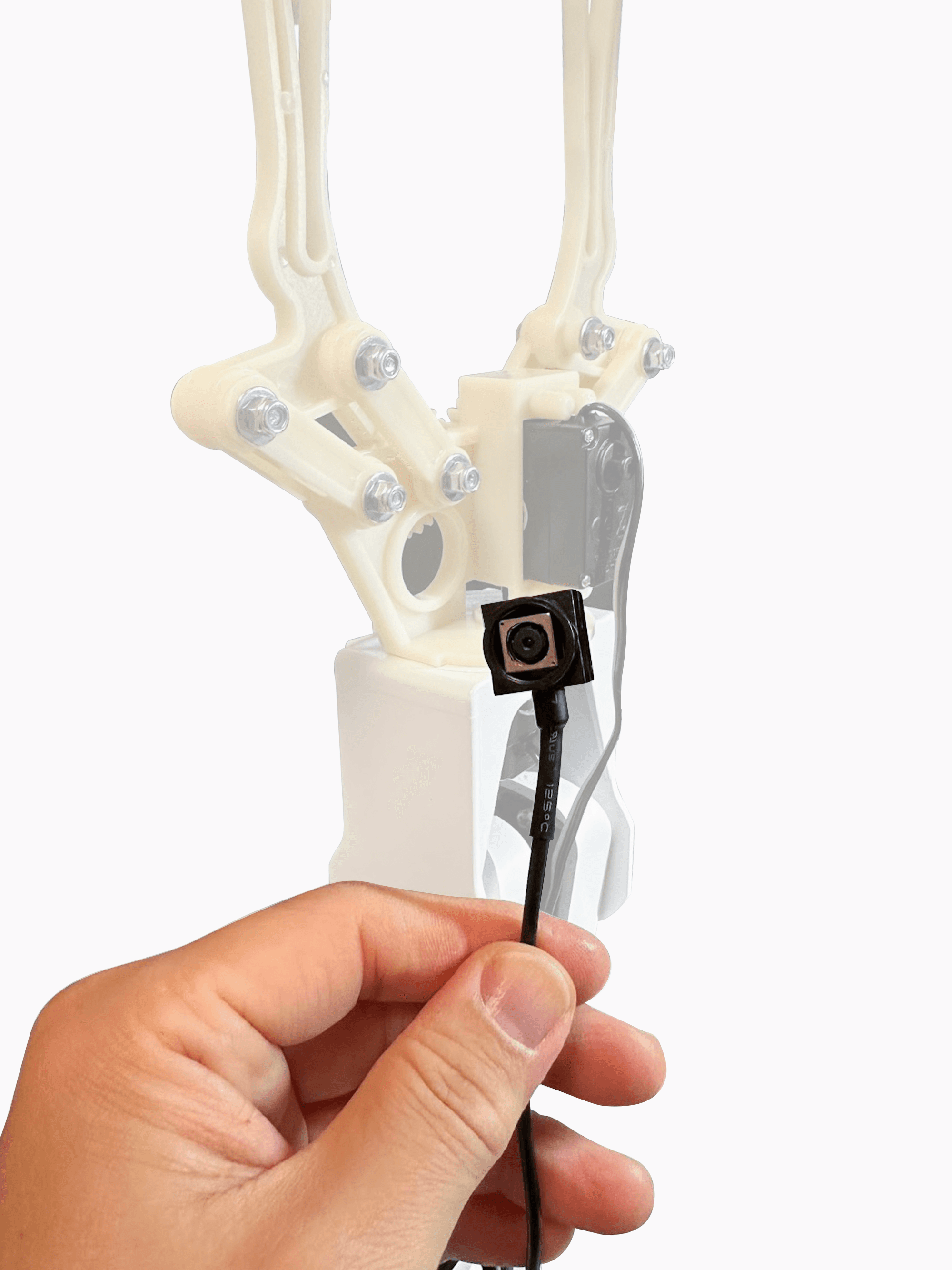
USB Camera.
The robot arm kit we used didn’t include an Arduino board, so we had to prepare our own. We used Arduino UNO R3 and assembled it with the board shield. Finally, the hardware for this medical prototype is ready.
2. How to make the robot arm move
You can use the Arduino example code to control the robot arm while receiving messages on ProtoPie Connect. Simply copy the example code and upload it to your Arduino board.
If you want to learn more, please refer to the following resources:
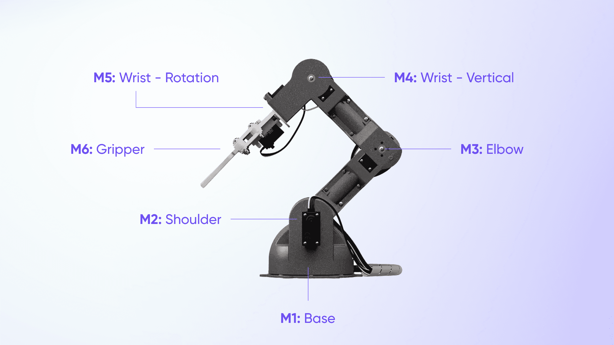
The robot arm has 6 servo motors. You can control each servo motor by sending a message through ProtoPie Connect.
Refer to the table below for the robot arm signals.
Robot arm signals.
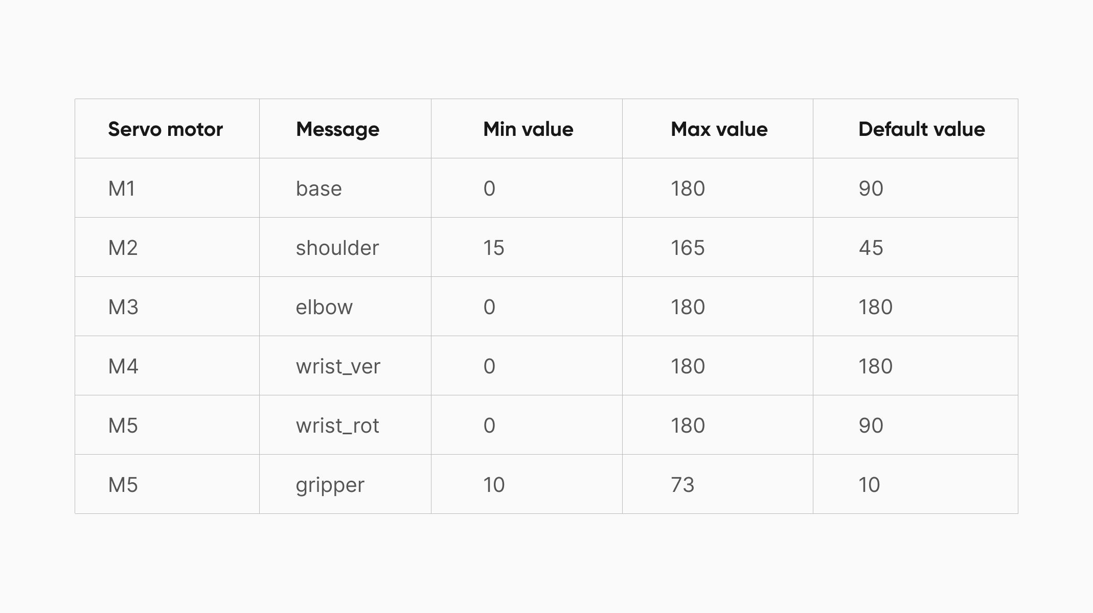
Robot arm signals.
Next, plug the Arduino board into your laptop through a USB cable and run ProtoPie Connect. Click on Plugin → Arduino → Port → and select USB port.
Next, press the ‘Run’ button on the Arduino plugin to activate it.
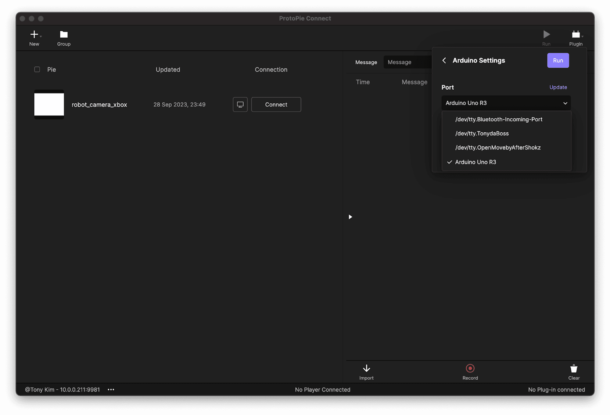
Arduino Connection.
Test if it works properly by sending messages. For example, you could test with this message: base, value: 45.
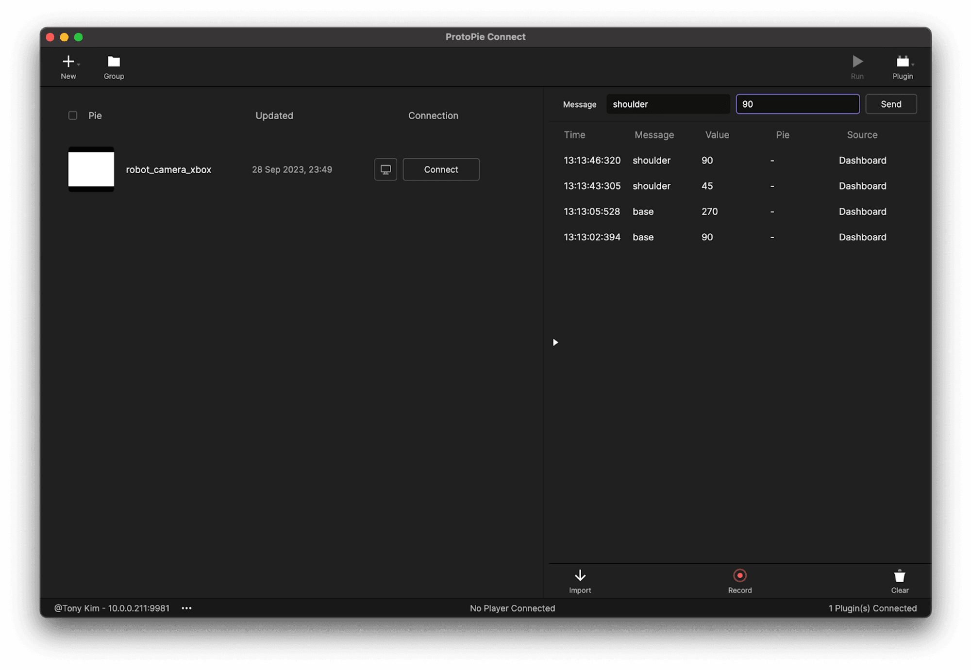
Test messages.
Test messages.
You can also type “reset” to reset to the original position.
3. Connect the wireless controller
Now it’s time to connect the wireless controller to your laptop through Bluetooth.
You need to run the gamepad plugin to receive signals from the gamepad. Learn more about the gamepad plugin.
Once the wireless controller is connected and the gamepad plugin is running, ProtoPie Connect can receive the signals. The table below shows the signals from the game controller.
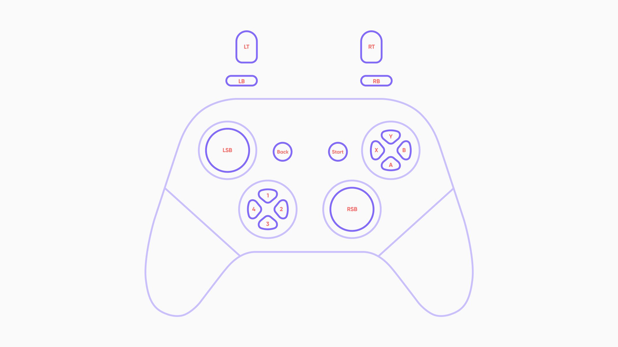
Console.
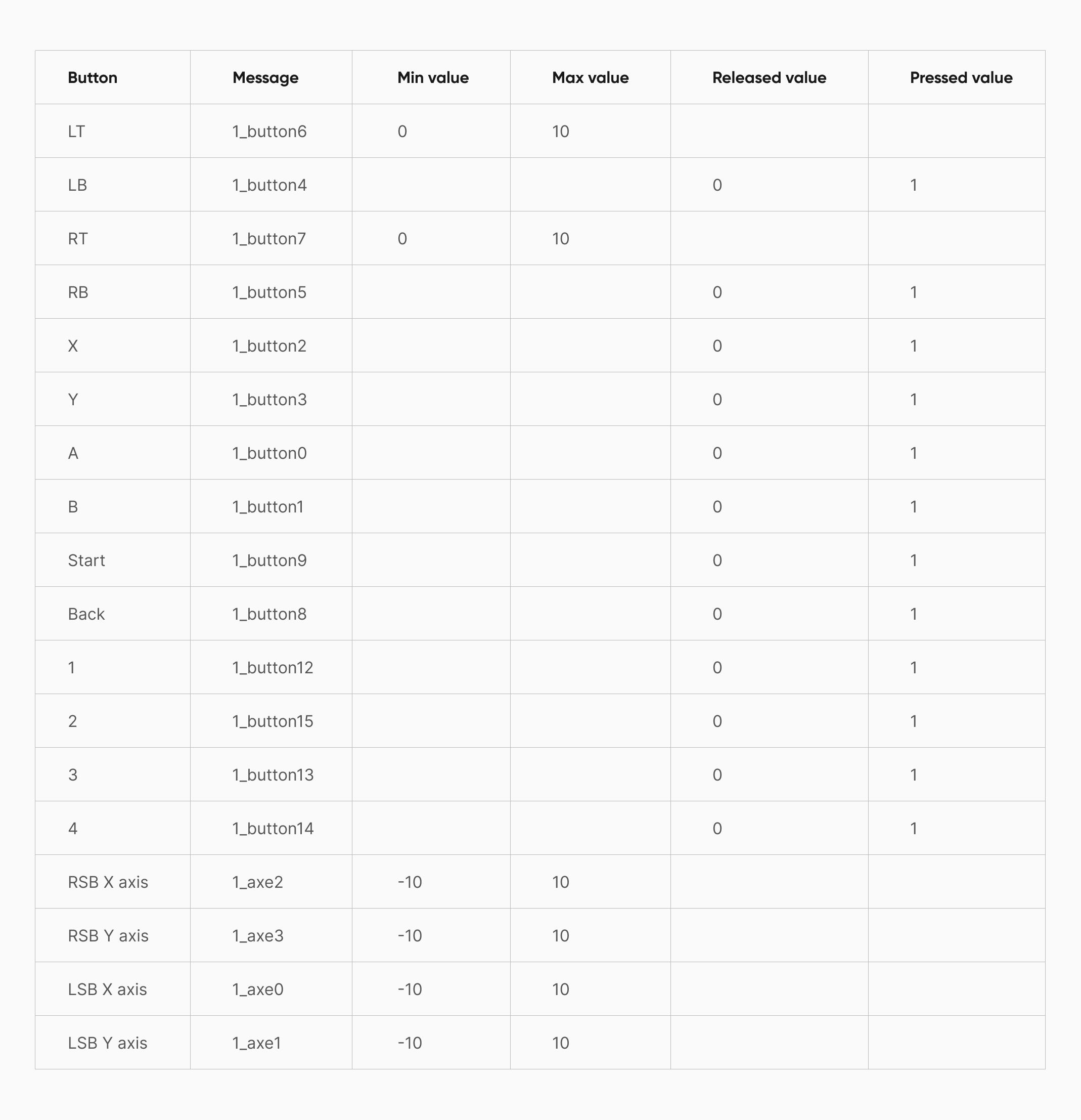
Controller Signals.
4. Bridge the wireless controller to Arduino
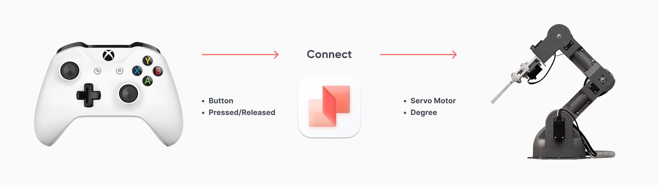
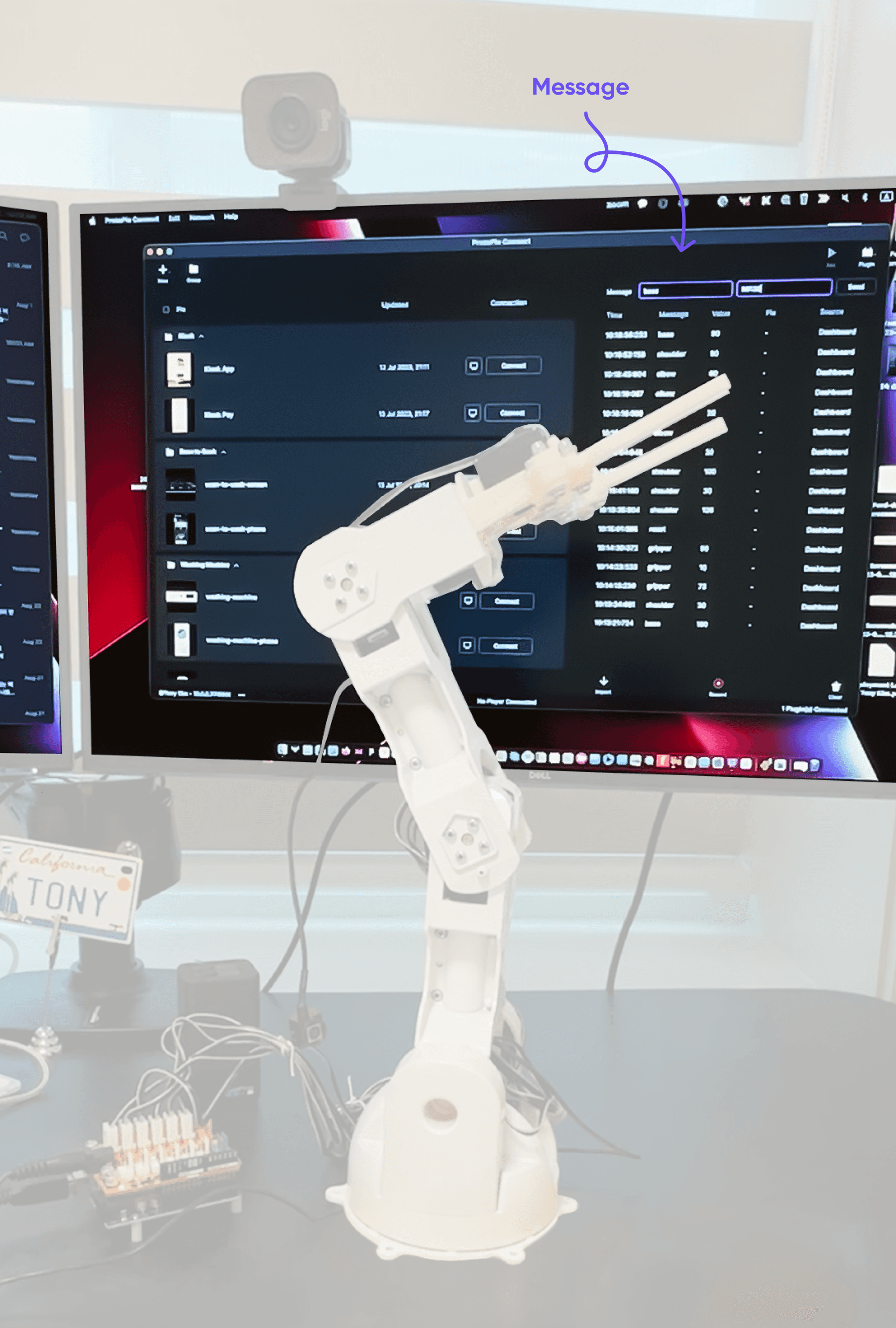
ProtoPie Connect is connecting the robot arm and the controller.
Controller.
Now that we connected the game controller, ProtoPie Connect receives the signals from the game controller and broadcasts them to Arduino.
Using ProtoPie, we prototyped a digital user interface for both controlling the robot arm and deciphering the signals exchanged between the game controller and Arduino. You can access and download the Pie file provided below for a closer look.
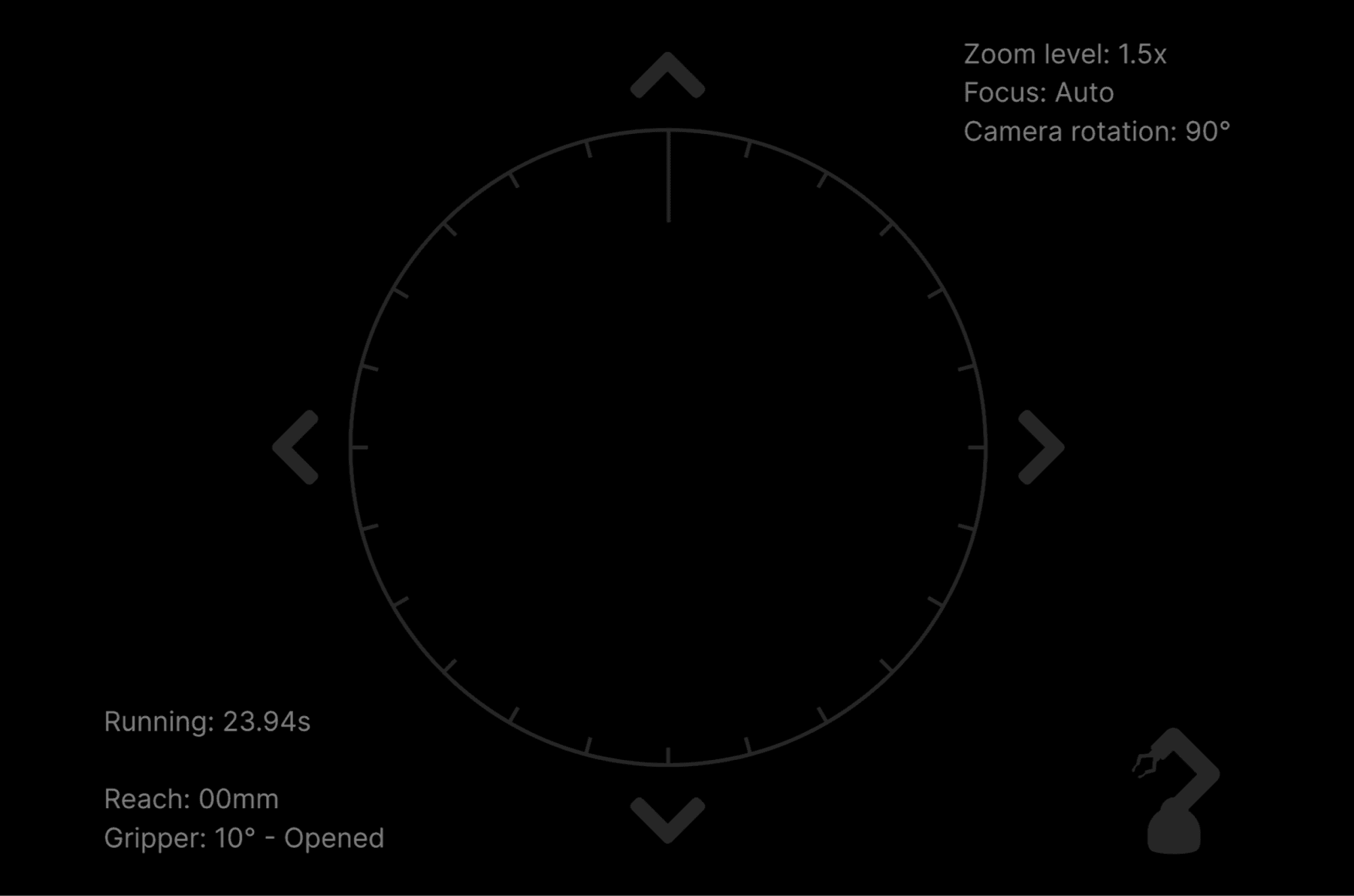
UI.
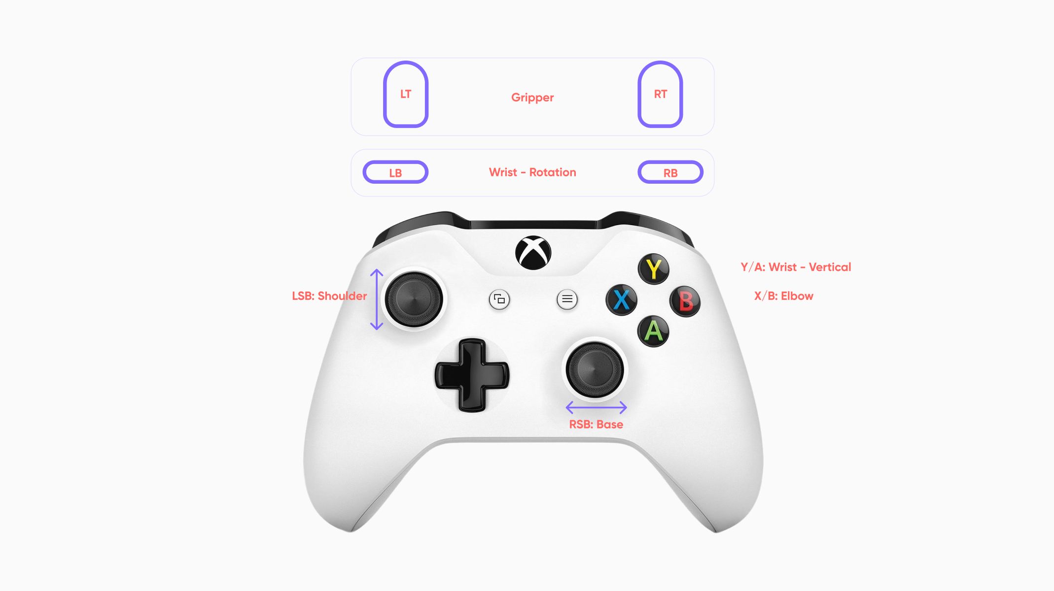
To control the base part of the robot arm (M1 servo motor), you can simply move the right thumb stick (RSB) left or right. The gamepad then sends a message (1_axe2 ) with a value (between -10 and 10) based on the stick movement.
ProtoPie Connect receives this message and the UI prototype (Pie) determines whether it's a positive or negative value. Positive means the base turns clockwise, while negative means counterclockwise. Next, the Pie sends a message (base) with a value (current degree plus/minus 5).
The Arduino-controlled robot arm receives this message, understands it, and starts moving accordingly. So, by moving the right thumb stick on the game controller, you can control the robot arm's base rotation.
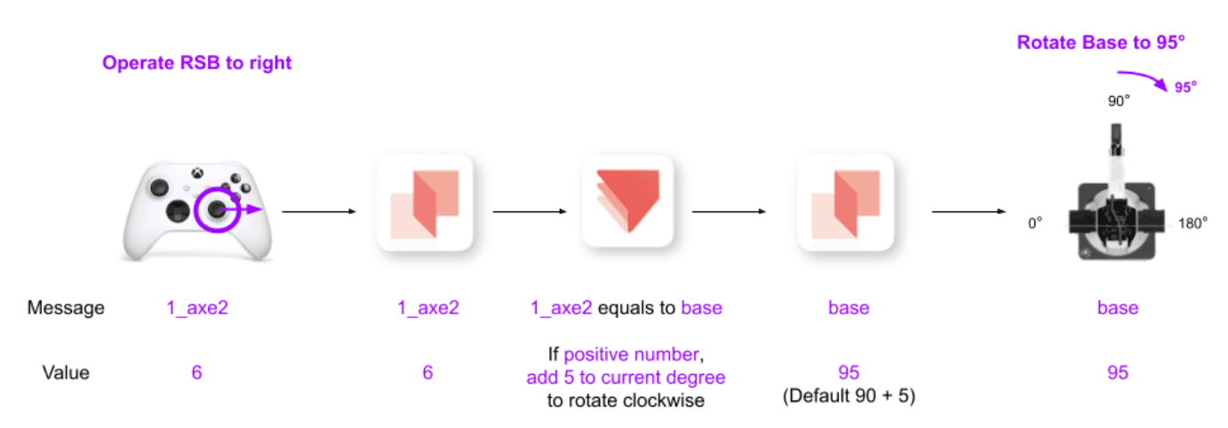
Pie interprets the messages and values from the controller for the Robot arm to understand.
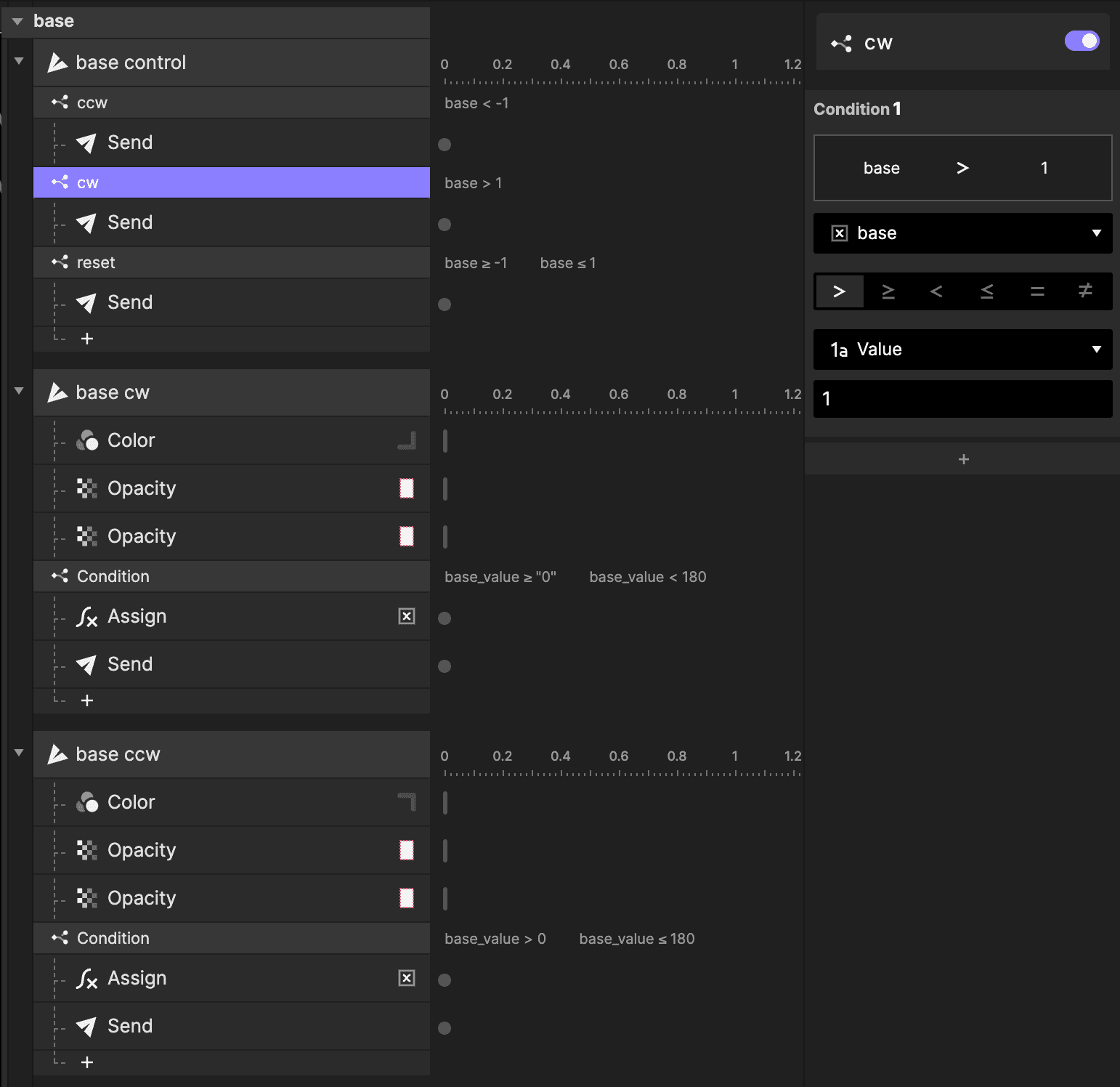
The condition checks whether the value is greater than 1.
5. Integrate a camera feed into the UI
The final piece of the puzzle is integrating a live camera feed into our UI. To accomplish this, you'll require a node server to overlay the Pie file onto the camera feed. The launch of ProtoPie Connect 2.7.0 brings an exciting update: the ability to integrate live camera feeds into robotics systems, significantly improving their perception and interactive functions.
Download the source files and follow the video tutorial below to create a camera feed in the digital UI.
The UI should look like the image below after integrating the camera feed.
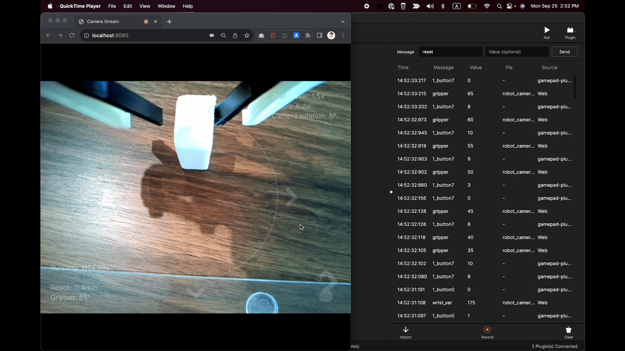
UI with live camera feed.
That’s it! The surgical robot arm prototype is complete
You’re all set! You successfully created a fully functional robot arm prototype. We are super excited to see which robotics prototypes you will create. Tag #MadeWithProtoPie on Social media and let us know!
Shape the future of Robotics and MedTech
In today's fast-evolving world of MedTech and robotics, staying ahead of the curve requires innovative tools. ProtoPie is at the forefront of advanced prototyping, offering unparalleled potential to reshape the future of robotics and the many industries that it’s currently revolutionizing, such as Manufacturing, Healthcare, Transportation, Logistics, and many more.
Download ProtoPie and get started today, or talk to one of our ProtoPie experts for more information.